220KV tension tower unmanned aerial vehicle (UAV) power line inspection: inspection points and standards
Simon.Srizfly
Table of Contents
Unmanned Aerial Vehicle (UAV) inspection of 220kV tension towers plays a vital role in ensuring the safety and reliability of high-voltage power transmission lines. Through high-resolution imaging and intelligent flight path planning, UAVs enable precise observation of key components such as insulators, fittings, and conductors. This inspection standard outlines the critical checkpoints, photographic requirements, and evaluation criteria to ensure that all captured images provide clear, measurable data for defect detection, maintenance assessment, and long-term asset management.
Serial Number
Inspection points
Shooting quality requirements
Software checkpoint screenshot
Real Inspection Point Images
1
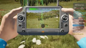
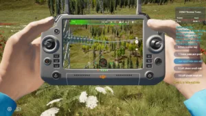
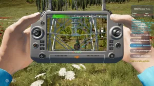
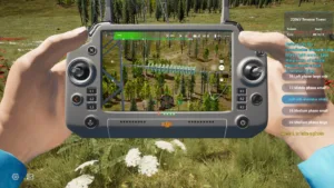
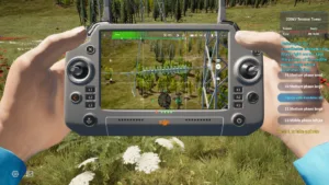
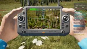
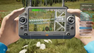
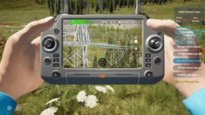
Tower Overview
The entire tower structure should be visible, clearly distinguishing tower materials and angles. The main structure (top to bottom) should occupy at least 80% of the image frame.
1 drone inspection tower overview
2
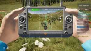
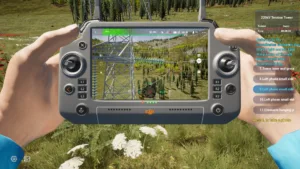
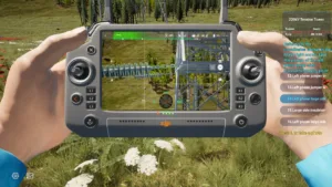
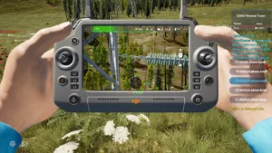
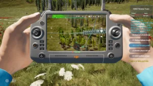
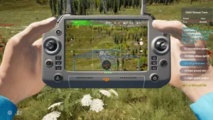
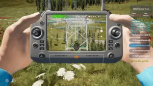
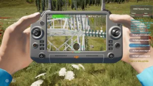
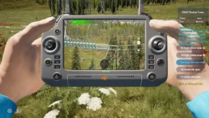
Tower Head
The top part of the tower should be fully visible.
2 drone inspection tower top
3
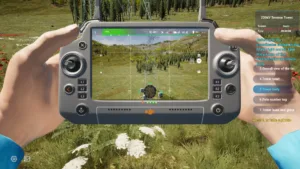
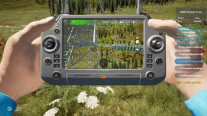
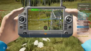
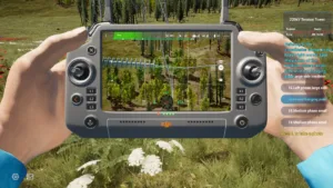
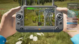
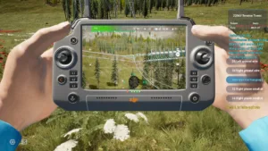
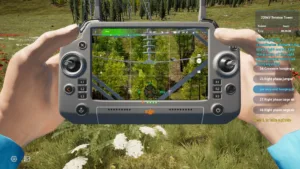
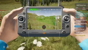
Tower Body
The entire body of the tower should be visible, excluding the tower head and base area.
3 drone inspection tower body
4
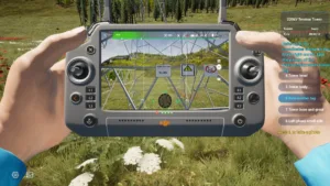
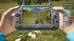
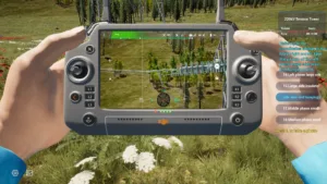
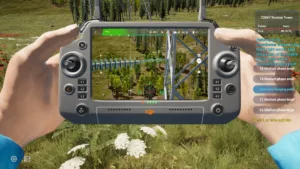
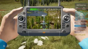
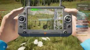
Pole Number Plate
The pole number plate should be clearly readable, showing dual line names.
4 drone inspection tower number plate
5
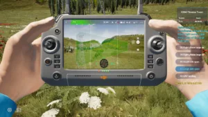
Tower Base and Ground
The area surrounding the tower base and nearby ground conditions should be clearly visible.
5 drone inspection tower base ground
6
Left Phase – Small Conductor Side – Conductor Suspension Point
Bolts, nuts, locking pins, and small-size fittings should be clearly visible, as well as vibration dampers. When components block each other, capture from multiple angles. Each photo must include at least one insulator disk.
6 drone inspection left phase small side wire terminal
7
Left Phase – Small Conductor Side – Insulator String
The entire insulator string should be covered. Multiple photos may be taken. The final image must clearly show surface damage and the connection of each insulator disk.
7 drone inspection left phase small side insulator string
8
Left Phase – Small Conductor Side – Crossarm Suspension Point
Bolts, nuts, locking pins, and small-size fittings should be clearly visible. When components block each other, capture from multiple angles. Each photo must include at least one insulator disk.
8 drone inspection left phase small side crossarm point
9
Left Phase – Jumper – Crossarm Suspension Point
Bolts, nuts, locking pins, and small-size fittings should be clearly visible. Capture from multiple angles if components block each other. Each photo must include at least one insulator disk.
9 drone inspection left phase jumper crossarm point
10
Left Phase – Jumper – Insulator String
The entire insulator string should be covered. Multiple photos may be taken. The final image must clearly show surface damage and each insulator disk’s connection.
10 drone inspection left phase jumper insulator string
11
Left Phase – Jumper – Conductor Suspension Point
Bolts, nuts, locking pins, and small-size fittings (including vibration dampers) should be clearly visible. Capture from multiple angles when equipment obstructs the view. Each photo must include at least one insulator disk.
11 drone inspection left phase jumper wire terminal
12
Left Phase – Large Conductor Side – Crossarm Suspension Point
Bolts, nuts, and locking pins should be clearly visible. Capture from multiple angles if components block each other. Each photo must include at least one insulator disk.
12 drone inspection left phase large side crossarm point
13
Left Phase – Large Conductor Side – Insulator String
The entire insulator string should be covered. Multiple photos may be taken to clearly identify surface damage and disk connections.
13 drone inspection left phase large side insulator string
14
Left Phase – Large Conductor Side – Conductor Suspension Point
Bolts, nuts, locking pins, and small-size fittings (including vibration dampers) should be clearly visible. Capture from multiple angles when equipment blocks the view. Each photo must include at least one insulator disk.
14 drone inspection left phase large side wire terminal
15
Middle Phase – Small Conductor Side – Conductor Suspension Point
Bolts, nuts, locking pins, and vibration dampers should be clearly visible. Capture from multiple angles when components overlap. Each photo must include at least one insulator disk.
15 drone inspection middle phase small side insulator string
16
Middle Phase – Small Conductor Side – Insulator String
The entire insulator string should be captured. Multiple photos may be taken. The final image should clearly show surface damage and each insulator disk’s connection.
16 drone inspection middle phase small side insulator string
17
Middle Phase – Small Conductor Side – Crossarm Suspension Point
Bolts, nuts, locking pins, and small-size fittings should be clearly visible. Capture from multiple angles if obstructed. Each photo must include at least one insulator disk.
17 drone inspection middle phase small side crossarm point
18
Middle Phase – Large Conductor Side – Crossarm Suspension Point
Bolts, nuts, locking pins, and small-size fittings should be clearly visible. Capture from multiple angles if obstructed. Each photo must include at least one insulator disk.
18 drone inspection middle phase large side crossarm point
19
Middle Phase – Large Conductor Side – Insulator String
The entire insulator string should be covered. Multiple photos may be taken. The final image must clearly show surface damage and disk connections.
19 drone inspection middle phase large side insulator string
20
Middle Phase – Large Conductor Side – Conductor Suspension Point
Bolts, nuts, locking pins, and vibration dampers should be clearly visible. Capture from multiple angles if obstructed. Each photo must include at least one insulator disk.
20 drone inspection middle phase large side wire terminal
21
Left Ground Wire
The combination state of fittings and the installation condition of the aluminum wrapping tape at the contact point with the ground wire should be visible. Bolts, nuts, and locking positions should be clearly identified. Capture from multiple angles if obstructed.
21 drone inspection left ground wire
22
Right Ground Wire
Same as left: clearly show the fittings, wrapping tape installation, and locking positions of nuts and bolts. Capture from multiple angles if obstructed.
22 drone inspection right ground wire
23
Middle Phase – Left Jumper – Crossarm Suspension Point
Bolts, nuts, and locking pins should be visible. Capture from multiple angles if obstructed. Each photo must include at least one insulator disk.
23 drone inspection middle phase left jumper crossarm point
24
Middle Phase – Left Jumper – Insulator String
The entire insulator string should be captured. Multiple photos may be taken. The final image must clearly show surface damage and disk connections.
24 drone inspection middle phase left jumper insulator string
25
Middle Phase – Left Jumper – Conductor Suspension Point
Bolts, nuts, locking pins, and vibration dampers should be clearly visible. Capture from multiple angles when obstructed. Each photo must include at least one insulator disk.
25 drone inspection middle phase left jumper wire terminal
26
Middle Phase – Right Jumper – Crossarm Suspension Point
Bolts, nuts, locking pins, and small-size fittings should be clearly visible. Capture from multiple angles if obstructed. Each photo must include at least one insulator disk.
26 drone inspection middle phase right jumper crossarm point
27
Middle Phase – Right Jumper – Insulator String
The entire insulator string should be covered. Multiple photos may be taken. The final image must clearly show surface damage and connections.
27 drone inspection middle phase right jumper insulator string
28
Middle Phase – Right Jumper – Conductor Suspension Point
Bolts, nuts, locking pins, and vibration dampers should be clearly visible. Capture from multiple angles if obstructed. Each photo must include at least one insulator disk.
28 drone inspection middle phase right jumper wire terminal
29
Right Phase – Small Conductor Side – Conductor Suspension Point
Bolts, nuts, locking pins, and vibration dampers should be clearly visible. Capture from multiple angles if obstructed. Each photo must include at least one insulator disk.
29 drone inspection right phase small side wire terminal
30
Right Phase – Small Conductor Side – Insulator String
The entire insulator string should be captured. Multiple photos may be taken. The final image must clearly show surface damage and connections.
30 drone inspection right phase small side insulator string
31
Right Phase – Small Conductor Side – Crossarm Suspension Point
Bolts, nuts, and locking pins should be clearly visible. Capture from multiple angles if obstructed. Each photo must include at least one insulator disk.
31 drone inspection right phase small side crossarm point
32
Right Phase – Jumper – Crossarm Suspension Point
Bolts, nuts, and locking pins should be clearly visible. Capture from multiple angles if obstructed. Each photo must include at least one insulator disk.
32 drone inspection right phase jumper crossarm point
33
Right Phase – Jumper – Insulator String
The entire insulator string should be covered. Multiple photos may be taken. The final image must clearly show surface damage and connections.
33 drone inspection right phase jumper insulator string
34
Right Phase – Jumper – Conductor Suspension Point
Bolts, nuts, locking pins, and vibration dampers should be clearly visible. Capture from multiple angles if obstructed. Each photo must include at least one insulator disk.
34 drone inspection right phase jumper wire terminal
35
Right Phase – Large Conductor Side – Crossarm Suspension Point
Bolts, nuts, and locking pins should be clearly visible. Capture from multiple angles if obstructed. Each photo must include at least one insulator disk.
35 drone inspection right phase large side crossarm point
36
Right Phase – Large Conductor Side – Insulator String
The entire insulator string should be covered. Multiple photos may be taken. The final image must clearly show surface damage and connections.
36 drone inspection right phase large side insulator string
37
Right Phase – Large Conductor Side – Conductor Suspension Point
Bolts, nuts, locking pins, and vibration dampers should be clearly visible. Capture from multiple angles if obstructed. Each photo must include at least one insulator disk.
37 drone inspection right phase large side wire terminal
38
Small Conductor Side – Corridor
The tower corridor should be clearly visible, including nearby structures, vegetation, crossing lines, and other surrounding conditions.
38 drone inspection small side access path
39
Large Conductor Side – Corridor
The tower corridor should be clearly visible, including nearby structures, vegetation, crossing lines, and other surrounding conditions.