500 kV Tension Tower: Key Inspection Points and Standards
Simon.Srizfly
Table of Contents
The 500 kV tension tower plays a critical role in high-voltage power transmission, ensuring stable and reliable delivery of electricity across long distances. Proper inspection of these towers is essential to maintain structural integrity, prevent line faults, and guarantee safety. This guide outlines the key inspection points and industry standards, helping technicians and UAV operators systematically assess tower components, including insulators, conductors, hardware fittings, and grounding systems, for efficient and safe maintenance operations.
Serial Number
Inspection points
Shooting quality requirements
Software checkpoint screenshot
Real Inspection Point Images
1
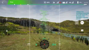
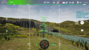
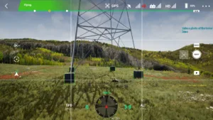
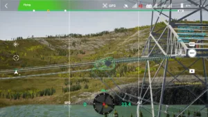
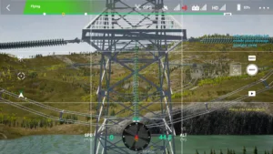
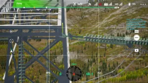
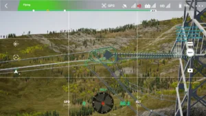
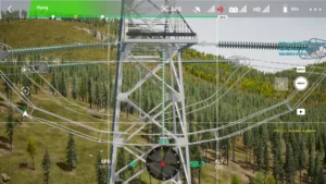
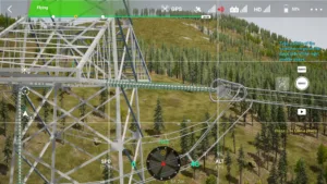
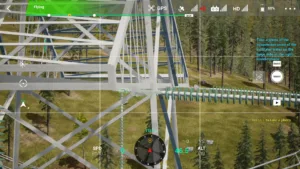
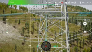
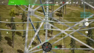
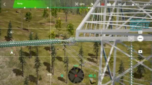
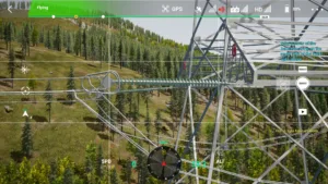
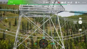
Full Tower View
The full tower view should be complete, clearly showing the tower materials and angles, with the main subject occupying at least 80% of the vertical frame.
All structures except the tower head and base must be visible.
03 tower body 500kv tension tower drone simulator
4
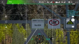
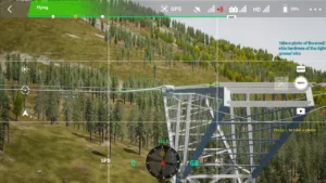
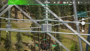
Pole Number Plate
The dual-line names on the pole number plate must be clearly distinguishable.
04 tower number plate 500kv tension tower drone simulator
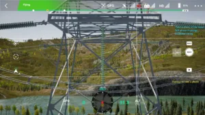
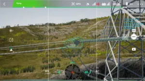
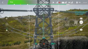
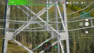
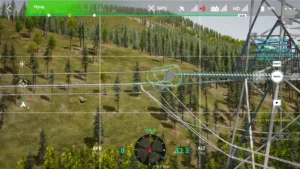
5
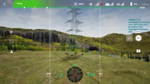
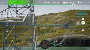
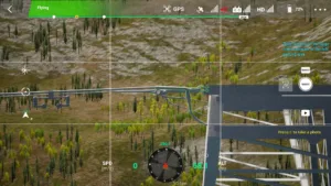
Tower Base
The ground condition near the tower base must be clear, and guy wires must be firmly connected.
05 tower base 500kv tension tower drone simulator
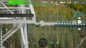
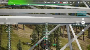
6
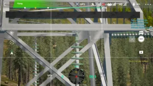
Left Lower Phase, Small-side Insulator Conductor End Hanger
Bolts, nuts, locking pins, and vibration dampers must be clearly visible. Use multiple angles if equipment overlaps. Each photo should include at least one insulator.
06 left lower small conductor end 500kv tension tower drone simulator
7
Left Lower Phase, Small-side Insulator
The full string of insulators must be covered. Multiple photos may be taken to clearly show surface damage and connections of each insulator.
07 left lower small insulator 500kv tension tower drone simulator
8
Left Lower Phase, Small-side Insulator Cross-arm End Hanger
Bolts, nuts, locking pins, and small hardware must be clearly visible. Use multiple angles if equipment overlaps. Each photo should include at least one insulator.
08 left lower small crossarm end 500kv tension tower drone simulator
9
Left Lower Phase, Jumper String Cross-arm End Hanger
Photograph the connecting hardware at the lower end of the hanger from a horizontal angle; take a top-down shot of bolts and pins above the hanger. Hardware should occupy at least 50% of the photo.
09 left lower jumper crossarm end 500kv tension tower drone simulator
10
Left Lower Phase, Jumper Insulator
Capture the full insulator; each shed must be clearly identifiable.
10 left lower jumper insulator 500kv tension tower drone simulator
11
Left Lower Phase, Jumper String Conductor End Hanger
Take two photos from small-side and large-side conductor ends. Each photo must show the panorama from the insulator’s end cup to the damper, with hardware occupying at least 50% of the photo.
11 left lower jumper conductor end 500kv tension tower drone simulator
12
Left Lower Phase, Large-side Insulator Cross-arm End Hanger
Bolts, nuts, locking pins, and small hardware must be clearly visible. Use multiple angles if equipment overlaps. Each photo should include at least one insulator.
12 left lower large crossarm end 500kv tension tower drone simulator
13
Left Lower Phase, Large-side Insulator
Cover the full insulator string; multiple photos may be taken to clearly show surface damage and connections of each insulator.
13 left lower large insulator 500kv tension tower drone simulator
14
Left Lower Phase, Large-side Insulator Conductor End Hanger
Bolts, nuts, locking pins, and vibration dampers must be clearly visible. Use multiple angles if equipment overlaps. Each photo should include at least one insulator.
14 left lower large conductor end 500kv tension tower drone simulator
15
Left Middle Phase, Small-side Insulator Conductor End Hanger
Bolts, nuts, locking pins, and vibration dampers must be clearly visible. Use multiple angles if equipment overlaps. Each photo should include at least one insulator.
15 left middle small conductor end 500kv tension tower drone simulator
16
Left Middle Phase, Small-side Insulator
Cover the full insulator string; multiple photos may be taken to clearly show surface damage and connections of each insulator.
16 left middle small insulator 500kv tension tower drone simulator
17
Left Middle Phase, Small-side Insulator Cross-arm End Hanger
Bolts, nuts, locking pins, and small hardware must be clearly visible. Use multiple angles if equipment overlaps. Each photo should include at least one insulator.
17 left middle small crossarm end 500kv tension tower drone simulator
18
Left Middle Phase, Jumper String Cross-arm End Hanger
Photograph the connecting hardware at the lower end from a horizontal angle; take a top-down shot of bolts and pins above the hanger. Hardware should occupy at least 50% of the photo.
18 left middle jumper crossarm end 500kv tension tower drone simulator
19
Left Middle Phase, Jumper Insulator
Capture the full insulator; each shed must be clearly identifiable.
19 left middle jumper insulator 500kv tension tower drone simulator
20
Left Middle Phase, Jumper String Conductor End Hanger
Take two photos from small-side and large-side conductor ends. Each photo must show the panorama from the insulator’s end cup to the damper, with hardware occupying at least 50% of the photo.
20 left middle jumper conductor end 500kv tension tower drone simulator
21
Left Middle Phase, Large-side Insulator Cross-arm End Hanger
Bolts, nuts, locking pins, and small hardware must be clearly visible. Use multiple angles if equipment overlaps. Each photo should include at least one insulator.
21 left middle large crossarm end 500kv tension tower drone simulator
22
Left Middle Phase, Large-side Insulator
Cover the full insulator string; multiple photos may be taken to clearly show surface damage and connections of each insulator.
22 left middle large insulator 500kv tension tower drone simulator
23
Left Middle Phase, Large-side Insulator Conductor End Hanger
Bolts, nuts, locking pins, and vibration dampers must be clearly visible. Use multiple angles if equipment overlaps. Each photo should include at least one insulator.
23 left middle large conductor end 500kv tension tower drone simulator
24
Left Upper Phase, Small-side Insulator Conductor End Hanger
Bolts, nuts, locking pins, and vibration dampers must be clearly visible. Use multiple angles if equipment overlaps. Each photo should include at least one insulator.
24 left upper small conductor end 500kv tension tower drone simulator
25
Left Upper Phase, Small-side Insulator
Cover the full insulator string; multiple photos may be taken to clearly show surface damage and connections of each insulator.
25 left upper small insulator 500kv tension tower drone simulator
26
Left Upper Phase, Small-side Insulator Cross-arm End Hanger
Bolts, nuts, locking pins, and small hardware must be clearly visible. Use multiple angles if equipment overlaps. Each photo should include at least one insulator.
26 left upper small crossarm end 500kv tension tower drone simulator
27
Left Upper Phase, Jumper String Cross-arm End Hanger
Photograph the connecting hardware at the lower end from a horizontal angle; take a top-down shot of bolts and pins above the hanger. Hardware should occupy at least 50% of the photo.
27 left upper jumper crossarm end 500kv tension tower drone simulator
28
Left Upper Phase, Jumper Insulator
Capture the full insulator; each shed must be clearly identifiable.
28 left upper jumper insulator 500kv tension tower drone simulator
29
Left Upper Phase, Jumper String Conductor End Hanger
Take two photos from small-side and large-side conductor ends. Each photo must show the panorama from the insulator’s end cup to the damper, with hardware occupying at least 50% of the photo.
29 left upper jumper conductor end 500kv tension tower drone simulator
30
Left Upper Phase, Large-side Insulator Cross-arm End Hanger
Bolts, nuts, locking pins, and small hardware must be clearly visible. Use multiple angles if equipment overlaps. Each photo should include at least one insulator.
30 left upper large crossarm end 500kv tension tower drone simulator
31
Left Upper Phase, Large-side Insulator
Cover the full insulator string; multiple photos may be taken to clearly show surface damage and connections of each insulator.
31 left upper large insulator 500kv tension tower drone simulator
32
Left Upper Phase, Large-side Insulator Conductor End Hanger
Bolts, nuts, locking pins, and vibration dampers must be clearly visible. Use multiple angles if equipment overlaps. Each photo should include at least one insulator.
32 left upper large conductor end 500kv tension tower drone simulator
33
Left Large-side Ground Wire Hanger
The combination installation status of all hardware should be identifiable, as well as the aluminum tape installation at the wire contact points. Nuts and pins at locking positions must be clearly visible. Use multiple angles if equipment overlaps.
33 left large ground end 500kv tension tower drone simulator
34
Left Small-side Ground Wire Hanger
The combination installation status of all hardware should be identifiable, as well as the aluminum tape installation at the wire contact points. Nuts and pins at locking positions must be clearly visible. Use multiple angles if equipment overlaps.
34 left small ground end 500kv tension tower drone simulator
35
Right Large-side Ground Wire Hanger
The combination installation status of all hardware should be identifiable, as well as the aluminum tape installation at the wire contact points. Nuts and pins at locking positions must be clearly visible. Use multiple angles if equipment overlaps.
35 right large ground end 500kv tension tower drone simulator
36
Right Small-side Ground Wire Hanger
The combination installation status of all hardware should be identifiable, as well as the aluminum tape installation at the wire contact points. Nuts and pins at locking positions must be clearly visible. Use multiple angles if equipment overlaps.
36 right small ground end 500kv tension tower drone simulator
37
Right Upper Phase, Small-side Insulator Conductor End Hanger
Bolts, nuts, locking pins, and vibration dampers must be clearly visible. Use multiple angles if equipment overlaps. Each photo should include at least one insulator.
37 right upper small conductor end 500kv tension tower drone simulator
38
Right Upper Phase, Small-side Insulator
Cover the full insulator string; multiple photos may be taken to clearly show surface damage and connections of each insulator.
38 right upper small insulator 500kv tension tower drone simulator
39
Right Upper Phase, Small-side Insulator Cross-arm End Hanger
Bolts, nuts, locking pins, and small hardware must be clearly visible. Use multiple angles if equipment overlaps. Each photo should include at least one insulator.
39 right upper small crossarm end 500kv tension tower drone simulator
40
Right Upper Phase, Jumper String Cross-arm End Hanger
Photograph the connecting hardware at the lower end from a horizontal angle; take a top-down shot of bolts and pins above the hanger. Hardware should occupy at least 50% of the photo.
40 right upper jumper crossarm end 500kv tension tower drone simulator
41
Right Upper Phase, Jumper Insulator
Capture the full insulator; each shed must be clearly identifiable.
41 right upper jumper insulator 500kv tension tower drone simulator
42
Right Upper Phase, Jumper String Conductor End Hanger
Take two photos from small-side and large-side conductor ends. Each photo must show the panorama from the insulator’s end cup to the damper, with hardware occupying at least 50% of the photo.
42 right upper jumper conductor end 500kv tension tower drone simulator
43
Right Upper Phase, Large-side Insulator Cross-arm End Hanger
Bolts, nuts, locking pins, and small hardware must be clearly visible. Use multiple angles if equipment overlaps. Each photo should include at least one insulator.
43 right upper large crossarm end 500kv tension tower drone simulator
44
Right Upper Phase, Large-side Insulator
Cover the full insulator string; multiple photos may be taken to clearly show surface damage and connections of each insulator.
44 right upper large insulator 500kv tension tower drone simulator
45
Right Upper Phase, Large-side Insulator Conductor End Hanger
Bolts, nuts, locking pins, and vibration dampers must be clearly visible. Use multiple angles if equipment overlaps. Each photo should include at least one insulator.
45 right upper large conductor end 500kv tension tower drone simulator
46
Right Middle Phase, Small-side Insulator Conductor End Hanger
Bolts, nuts, locking pins, and vibration dampers must be clearly visible. Use multiple angles if equipment overlaps. Each photo should include at least one insulator.
46 right middle small conductor end 500kv tension tower drone simulator
47
Right Middle Phase, Small-side Insulator
Cover the full insulator string; multiple photos may be taken to clearly show surface damage and connections of each insulator.
47 right middle small insulator 500kv tension tower drone simulator
48
Right Middle Phase, Small-side Insulator Cross-arm End Hanger
Bolts, nuts, locking pins, and small hardware must be clearly visible. Use multiple angles if equipment overlaps. Each photo should include at least one insulator.
48 right middle small crossarm end 500kv tension tower drone simulator
49
Right Middle Phase, Jumper String Cross-arm End Hanger
Photograph the connecting hardware at the lower end from a horizontal angle; take a top-down shot of bolts and pins above the hanger. Hardware should occupy at least 50% of the photo.
49 right middle jumper crossarm end 500kv tension tower drone simulator
50
Right Middle Phase, Jumper Insulator
Capture the full insulator; each shed must be clearly identifiable.
50 right middle jumper insulator 500kv tension tower drone simulator
51
Right Middle Phase, Jumper String Conductor End Hanger
Take two photos from small-side and large-side conductor ends. Each photo must show the panorama from the insulator’s end cup to the damper, with hardware occupying at least 50% of the photo.
51 right middle jumper conductor end 500kv tension tower drone simulator
52
Right Middle Phase, Large-side Insulator Cross-arm End Hanger
Bolts, nuts, locking pins, and small hardware must be clearly visible. Use multiple angles if equipment overlaps. Each photo should include at least one insulator.
52 right middle large crossarm end 500kv tension tower drone simulator
53
Right Middle Phase, Large-side Insulator
Cover the full insulator string; multiple photos may be taken to clearly show surface damage and connections of each insulator.
53 right middle large insulator 500kv tension tower drone simulator
54
Right Middle Phase, Large-side Insulator Conductor End Hanger
Bolts, nuts, locking pins, and vibration dampers must be clearly visible. Use multiple angles if equipment overlaps. Each photo should include at least one insulator.
54 right middle large conductor end 500kv tension tower drone simulator
55
Right Lower Phase, Small-side Insulator Conductor End Hanger
Bolts, nuts, locking pins, and vibration dampers must be clearly visible. Use multiple angles if equipment overlaps. Each photo should include at least one insulator.
55 right lower small conductor end 500kv tension tower drone simulator
56
Right Lower Phase, Small-side Insulator
Cover the full insulator string; multiple photos may be taken to clearly show surface damage and connections of each insulator.
56 right lower small insulator 500kv tension tower drone simulator
57
Right Lower Phase, Small-side Insulator Cross-arm End Hanger
Bolts, nuts, locking pins, and small hardware must be clearly visible. Use multiple angles if equipment overlaps. Each photo should include at least one insulator.
57 right lower small crossarm end 500kv tension tower drone simulator
58
Right Lower Phase, Jumper String Cross-arm End Hanger
Photograph the connecting hardware at the lower end from a horizontal angle; take a top-down shot of bolts and pins above the hanger. Hardware should occupy at least 50% of the photo.
58 right lower jumper crossarm end 500kv tension tower drone simulator
59
Right Lower Phase, Jumper Insulator
Capture the full insulator; each shed must be clearly identifiable.
59 right lower jumper insulator 500kv tension tower drone simulator
60
Right Lower Phase, Jumper String Conductor End Hanger
Take two photos from small-side and large-side conductor ends. Each photo must show the panorama from the insulator’s end cup to the damper, with hardware occupying at least 50% of the photo.
60 right lower jumper conductor end 500kv tension tower drone simulator
61
Right Lower Phase, Large-side Insulator Cross-arm End Hanger
Bolts, nuts, locking pins, and small hardware must be clearly visible. Use multiple angles if equipment overlaps. Each photo should include at least one insulator.
61 right lower large crossarm end 500kv tension tower drone simulator
62
Right Lower Phase, Large-side Insulator
Cover the full insulator string; multiple photos may be taken to clearly show surface damage and connections of each insulator.
62 right lower large insulator 500kv tension tower drone simulator
63
Right Lower Phase, Large-side Insulator Conductor End Hanger
Bolts, nuts, locking pins, and vibration dampers must be clearly visible. Use multiple angles if equipment overlaps. Each photo should include at least one insulator.
63 right lower large conductor end 500kv tension tower drone simulator
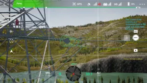
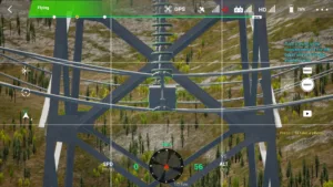
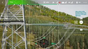
64
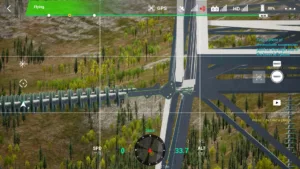
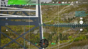
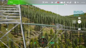
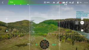
Small-side Passage
The tower passage should be fully visible, including buildings, trees, crossing points, and lines being spanned.
64 small side access path 500kv tension tower drone simulator
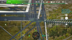
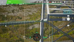
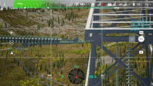
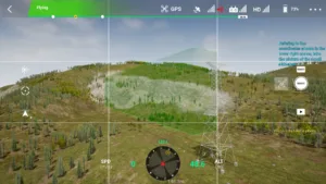
65
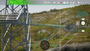
Large-side Passage
The tower passage should be fully visible, including buildings, trees, crossing points, and lines being spanned.
65 large side access path 500kv tension tower drone simulator