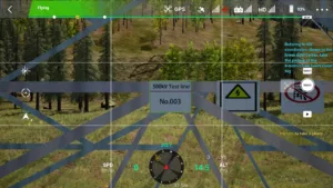
500kV linear tower power line inspection: Inspection points and standards
Simon.Srizfly
Table of Contents
The 500kV linear tower is a key component of ultra-high-voltage transmission networks, playing a critical role in delivering electricity over long distances. Regular inspections are essential to ensure structural integrity, operational safety, and the reliability of power delivery. This article outlines the essential inspection points and industry standards for UAV-based inspections, covering tower structures, insulators, conductors, and grounding systems. By following these guidelines, operators can efficiently detect potential faults, prevent failures, and maintain the safe and stable operation of high-voltage power lines.
Serial Number
Inspection points
Shooting quality requirements
Software checkpoint screenshot
Real Inspection Point Images
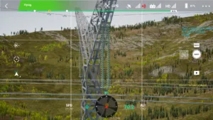
1
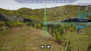
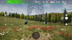
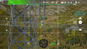
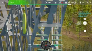
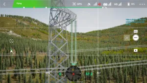
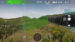
Tower Overview
The entire tower structure should be complete, with materials and tower angles clearly distinguishable. The main structure (top to bottom) should occupy at least 80% of the image frame.
1 full view 500kv linear tower drone simulator
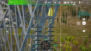
2
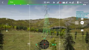
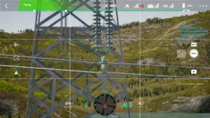
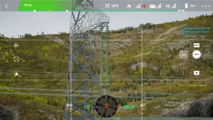
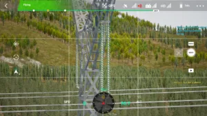
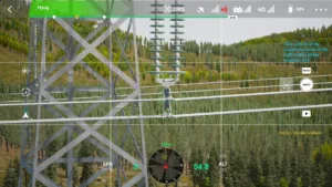
Tower Head
The tower head should be fully visible.
2 tower top 500kv drone simulator
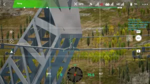
3
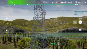
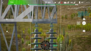
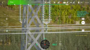
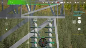
Tower Body
The full tower body (excluding the tower head and base) should be visible.
3 tower body 500kv drone simulator
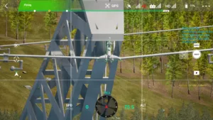
4
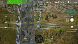
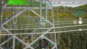
Pole Number Plate
The pole number plate should be clear enough to identify dual circuit line names.
4 tower number plate 500kv drone simulator
5
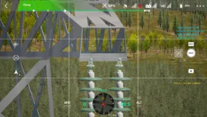
Tower Base
The surrounding ground condition near the tower base should be clearly visible.
5 tower base 500kv drone simulator
6
Left Circuit – Lower Phase – Conductor Suspension Point
Bolts, nuts, locking pins, and small fittings (including vibration dampers) must be clearly visible. If components block each other, take photos from multiple angles. Each photo must include at least one insulator disk.
6 left lower phase conductor end 500kv drone simulator
7
Left Circuit – Lower Phase – Insulator String
The entire insulator string should be covered. Multiple photos may be taken. The final image must clearly show surface damage and the connection of each insulator disk.
7 left lower phase insulator 500kv drone simulator
8
Left Circuit – Lower Phase – Crossarm Suspension Point
Bolts, nuts, and locking pins must be clearly visible. Take photos from multiple angles if components block each other. Each photo must include at least one insulator disk.
8 left lower crossarm end 500kv drone simulator
9
Left Circuit – Middle Phase – Conductor Suspension Point
Bolts, nuts, locking pins, and small fittings (including vibration dampers) must be clearly visible. If components block each other, take multiple angles. Each photo must include at least one insulator disk.
9 left middle phase conductor end 500kv drone simulator
10
Left Circuit – Middle Phase – Insulator String
The entire insulator string should be covered. Multiple photos may be taken. The final image must clearly show surface damage and connections of each insulator disk.
10 left middle phase insulator 500kv drone simulator
11
Left Circuit – Middle Phase – Crossarm Suspension Point
Bolts, nuts, and locking pins must be clearly visible. Take photos from multiple angles if components block each other. Each photo must include at least one insulator disk.
11 left middle crossarm end 500kv drone simulator
12
Left Circuit – Upper Phase – Conductor Suspension Point
Bolts, nuts, locking pins, and vibration dampers must be clearly visible. If equipment obstructs the view, capture from multiple angles. Each photo must include at least one insulator disk.
12 left upper phase conductor end 500kv drone simulator
13
Left Circuit – Upper Phase – Insulator String
The entire insulator string should be covered. Multiple photos may be taken. The final image must clearly show surface damage and connections of each insulator disk.
13 left upper phase insulator 500kv drone simulator
14
Left Circuit – Upper Phase – Crossarm Suspension Point
Bolts, nuts, and locking pins must be clearly visible. If components block each other, take photos from multiple angles. Each photo must include at least one insulator disk.
14 left upper crossarm end 500kv drone simulator
15
Left Circuit – Ground Wire
The installation and combination state of fittings and aluminum wrapping tape at the ground wire contact point should be visible. Bolts, nuts, and locking components should be clearly identifiable. If obstructed, take photos from multiple angles.
15 left ground wire 500kv drone simulator
16
Right Circuit – Ground Wire
The installation and combination state of fittings and aluminum wrapping tape at the ground wire contact point should be visible. Bolts, nuts, and locking components should be clearly identifiable. Take photos from multiple angles if obstructed.
16 right ground wire 500kv drone simulator
17
Right Circuit – Upper Phase – Crossarm Suspension Point
Bolts, nuts, and locking pins must be clearly visible. If components block each other, capture from multiple angles. Each photo must include at least one insulator disk.
17 right upper crossarm end 500kv drone simulator
18
Right Circuit – Upper Phase – Insulator String
The entire insulator string should be covered. Multiple photos may be taken. The final image must clearly show surface damage and connections of each insulator disk.
18 right upper phase insulator 500kv drone simulator
19
Right Circuit – Upper Phase – Conductor Suspension Point
Bolts, nuts, locking pins, and vibration dampers must be clearly visible. Capture from multiple angles if obstructed. Each photo must include at least one insulator disk.
19 right upper phase conductor end 500kv drone simulator
20
Right Circuit – Middle Phase – Crossarm Suspension Point
Bolts, nuts, and locking pins must be clearly visible. If components block each other, capture from multiple angles. Each photo must include at least one insulator disk.
20 right middle crossarm end 500kv drone simulator
21
Right Circuit – Middle Phase – Insulator String
The entire insulator string should be covered. Multiple photos may be taken. The final image must clearly show surface damage and connections of each insulator disk.
21 right middle phase insulator 500kv drone simulator
22
Right Circuit – Middle Phase – Conductor Suspension Point
Bolts, nuts, locking pins, and vibration dampers must be clearly visible. If components block each other, capture from multiple angles. Each photo must include at least one insulator disk.
22 right middle phase conductor end 500kv drone simulator
23
Right Circuit – Lower Phase – Crossarm Suspension Point
Bolts, nuts, and locking pins must be clearly visible. If components block each other, capture from multiple angles. Each photo must include at least one insulator disk.
23 right lower crossarm end 500kv drone simulator
24
Right Circuit – Lower Phase – Insulator String
The entire insulator string should be covered. Multiple photos may be taken. The final image must clearly show surface damage and connections of each insulator disk.
24 right lower phase insulator 500kv drone simulator
25
Right Circuit – Lower Phase – Conductor Suspension Point
Bolts, nuts, locking pins, and vibration dampers must be clearly visible. Capture from multiple angles if obstructed. Each photo must include at least one insulator disk.
25 right lower phase conductor end 500kv drone simulator
26
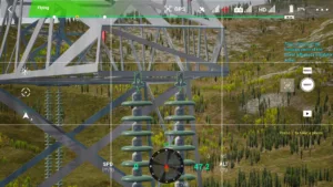
Small Conductor Side – Corridor
The tower corridor should be clearly and completely visible, including nearby buildings, vegetation, crossing lines, and other environmental conditions.
26 narrow side access path 500kv drone simulator
27
Large Conductor Side – Corridor
The tower corridor should be clearly and completely visible, including nearby buildings, vegetation, crossing lines, and other environmental conditions.