| Serial Number | Inspection points | Shooting quality requirements | Software checkpoint screenshot | Real Inspection Point Images |
|---|---|---|---|---|
| 1 | Full Tower View | The full tower view should be complete, clearly showing the tower materials and angles, with the main subject occupying at least 80% of the vertical frame. |  | |
| 2 | Tower Head | The tower head must be fully visible. |  | |
| 3 | Tower Body | All structures except the tower head and base must be visible. |  | |
| 4 | Pole Number Plate | The dual-line names on the pole number plate must be clearly distinguishable. |  | |
| 5 | Tower Base | The ground condition near the tower base must be clear, and guy wires must be firmly connected. |  | |
| 6 | Left Lower Phase, Small-side Insulator Conductor End Hanger | Bolts, nuts, locking pins, and vibration dampers must be clearly visible. Use multiple angles if equipment overlaps. Each photo should include at least one insulator. | 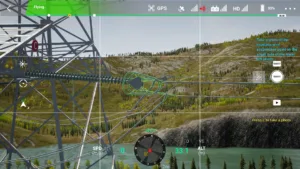 | |
| 7 | Left Lower Phase, Small-side Insulator | The full string of insulators must be covered. Multiple photos may be taken to clearly show surface damage and connections of each insulator. |  | |
| 8 | Left Lower Phase, Small-side Insulator Cross-arm End Hanger | Bolts, nuts, locking pins, and small hardware must be clearly visible. Use multiple angles if equipment overlaps. Each photo should include at least one insulator. |  | |
| 9 | Left Lower Phase, Jumper String Cross-arm End Hanger | Photograph the connecting hardware at the lower end of the hanger from a horizontal angle; take a top-down shot of bolts and pins above the hanger. Hardware should occupy at least 50% of the photo. |  | |
| 10 | Left Lower Phase, Jumper Insulator | Capture the full insulator; each shed must be clearly identifiable. | 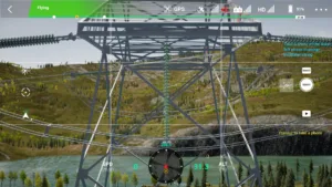 | |
| 11 | Left Lower Phase, Jumper String Conductor End Hanger | Take two photos from small-side and large-side conductor ends. Each photo must show the panorama from the insulator’s end cup to the damper, with hardware occupying at least 50% of the photo. |  | |
| 12 | Left Lower Phase, Large-side Insulator Cross-arm End Hanger | Bolts, nuts, locking pins, and small hardware must be clearly visible. Use multiple angles if equipment overlaps. Each photo should include at least one insulator. |  | |
| 13 | Left Lower Phase, Large-side Insulator | Cover the full insulator string; multiple photos may be taken to clearly show surface damage and connections of each insulator. |  | |
| 14 | Left Lower Phase, Large-side Insulator Conductor End Hanger | Bolts, nuts, locking pins, and vibration dampers must be clearly visible. Use multiple angles if equipment overlaps. Each photo should include at least one insulator. | 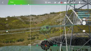 | |
| 15 | Left Middle Phase, Small-side Insulator Conductor End Hanger | Bolts, nuts, locking pins, and vibration dampers must be clearly visible. Use multiple angles if equipment overlaps. Each photo should include at least one insulator. | 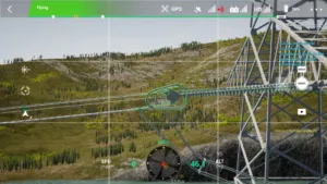 | |
| 16 | Left Middle Phase, Small-side Insulator | Cover the full insulator string; multiple photos may be taken to clearly show surface damage and connections of each insulator. |  | |
| 17 | Left Middle Phase, Small-side Insulator Cross-arm End Hanger | Bolts, nuts, locking pins, and small hardware must be clearly visible. Use multiple angles if equipment overlaps. Each photo should include at least one insulator. | 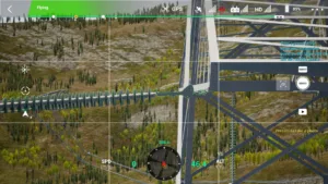 | |
| 18 | Left Middle Phase, Jumper String Cross-arm End Hanger | Photograph the connecting hardware at the lower end from a horizontal angle; take a top-down shot of bolts and pins above the hanger. Hardware should occupy at least 50% of the photo. |  | |
| 19 | Left Middle Phase, Jumper Insulator | Capture the full insulator; each shed must be clearly identifiable. | 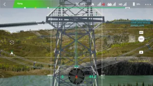 | |
| 20 | Left Middle Phase, Jumper String Conductor End Hanger | Take two photos from small-side and large-side conductor ends. Each photo must show the panorama from the insulator’s end cup to the damper, with hardware occupying at least 50% of the photo. |  | |
| 21 | Left Middle Phase, Large-side Insulator Cross-arm End Hanger | Bolts, nuts, locking pins, and small hardware must be clearly visible. Use multiple angles if equipment overlaps. Each photo should include at least one insulator. | 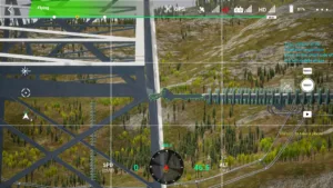 | |
| 22 | Left Middle Phase, Large-side Insulator | Cover the full insulator string; multiple photos may be taken to clearly show surface damage and connections of each insulator. | 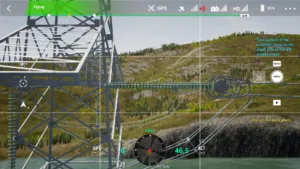 | |
| 23 | Left Middle Phase, Large-side Insulator Conductor End Hanger | Bolts, nuts, locking pins, and vibration dampers must be clearly visible. Use multiple angles if equipment overlaps. Each photo should include at least one insulator. |  | |
| 24 | Left Upper Phase, Small-side Insulator Conductor End Hanger | Bolts, nuts, locking pins, and vibration dampers must be clearly visible. Use multiple angles if equipment overlaps. Each photo should include at least one insulator. |  | |
| 25 | Left Upper Phase, Small-side Insulator | Cover the full insulator string; multiple photos may be taken to clearly show surface damage and connections of each insulator. |  | |
| 26 | Left Upper Phase, Small-side Insulator Cross-arm End Hanger | Bolts, nuts, locking pins, and small hardware must be clearly visible. Use multiple angles if equipment overlaps. Each photo should include at least one insulator. |  | |
| 27 | Left Upper Phase, Jumper String Cross-arm End Hanger | Photograph the connecting hardware at the lower end from a horizontal angle; take a top-down shot of bolts and pins above the hanger. Hardware should occupy at least 50% of the photo. |  | |
| 28 | Left Upper Phase, Jumper Insulator | Capture the full insulator; each shed must be clearly identifiable. |  | |
| 29 | Left Upper Phase, Jumper String Conductor End Hanger | Take two photos from small-side and large-side conductor ends. Each photo must show the panorama from the insulator’s end cup to the damper, with hardware occupying at least 50% of the photo. |  | |
| 30 | Left Upper Phase, Large-side Insulator Cross-arm End Hanger | Bolts, nuts, locking pins, and small hardware must be clearly visible. Use multiple angles if equipment overlaps. Each photo should include at least one insulator. |  | |
| 31 | Left Upper Phase, Large-side Insulator | Cover the full insulator string; multiple photos may be taken to clearly show surface damage and connections of each insulator. |  | |
| 32 | Left Upper Phase, Large-side Insulator Conductor End Hanger | Bolts, nuts, locking pins, and vibration dampers must be clearly visible. Use multiple angles if equipment overlaps. Each photo should include at least one insulator. |  | |
| 33 | Left Large-side Ground Wire Hanger | The combination installation status of all hardware should be identifiable, as well as the aluminum tape installation at the wire contact points. Nuts and pins at locking positions must be clearly visible. Use multiple angles if equipment overlaps. | 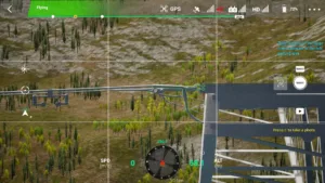 | |
| 34 | Left Small-side Ground Wire Hanger | The combination installation status of all hardware should be identifiable, as well as the aluminum tape installation at the wire contact points. Nuts and pins at locking positions must be clearly visible. Use multiple angles if equipment overlaps. |  | |
| 35 | Right Large-side Ground Wire Hanger | The combination installation status of all hardware should be identifiable, as well as the aluminum tape installation at the wire contact points. Nuts and pins at locking positions must be clearly visible. Use multiple angles if equipment overlaps. |  | |
| 36 | Right Small-side Ground Wire Hanger | The combination installation status of all hardware should be identifiable, as well as the aluminum tape installation at the wire contact points. Nuts and pins at locking positions must be clearly visible. Use multiple angles if equipment overlaps. | 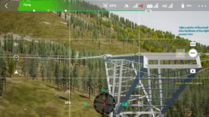 | |
| 37 | Right Upper Phase, Small-side Insulator Conductor End Hanger | Bolts, nuts, locking pins, and vibration dampers must be clearly visible. Use multiple angles if equipment overlaps. Each photo should include at least one insulator. |  | |
| 38 | Right Upper Phase, Small-side Insulator | Cover the full insulator string; multiple photos may be taken to clearly show surface damage and connections of each insulator. |  | |
| 39 | Right Upper Phase, Small-side Insulator Cross-arm End Hanger | Bolts, nuts, locking pins, and small hardware must be clearly visible. Use multiple angles if equipment overlaps. Each photo should include at least one insulator. |  | |
| 40 | Right Upper Phase, Jumper String Cross-arm End Hanger | Photograph the connecting hardware at the lower end from a horizontal angle; take a top-down shot of bolts and pins above the hanger. Hardware should occupy at least 50% of the photo. | 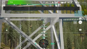 | |
| 41 | Right Upper Phase, Jumper Insulator | Capture the full insulator; each shed must be clearly identifiable. | 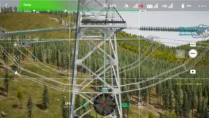 | |
| 42 | Right Upper Phase, Jumper String Conductor End Hanger | Take two photos from small-side and large-side conductor ends. Each photo must show the panorama from the insulator’s end cup to the damper, with hardware occupying at least 50% of the photo. |  | |
| 43 | Right Upper Phase, Large-side Insulator Cross-arm End Hanger | Bolts, nuts, locking pins, and small hardware must be clearly visible. Use multiple angles if equipment overlaps. Each photo should include at least one insulator. |  | |
| 44 | Right Upper Phase, Large-side Insulator | Cover the full insulator string; multiple photos may be taken to clearly show surface damage and connections of each insulator. |  | |
| 45 | Right Upper Phase, Large-side Insulator Conductor End Hanger | Bolts, nuts, locking pins, and vibration dampers must be clearly visible. Use multiple angles if equipment overlaps. Each photo should include at least one insulator. |  | |
| 46 | Right Middle Phase, Small-side Insulator Conductor End Hanger | Bolts, nuts, locking pins, and vibration dampers must be clearly visible. Use multiple angles if equipment overlaps. Each photo should include at least one insulator. |  | |
| 47 | Right Middle Phase, Small-side Insulator | Cover the full insulator string; multiple photos may be taken to clearly show surface damage and connections of each insulator. |  | |
| 48 | Right Middle Phase, Small-side Insulator Cross-arm End Hanger | Bolts, nuts, locking pins, and small hardware must be clearly visible. Use multiple angles if equipment overlaps. Each photo should include at least one insulator. | 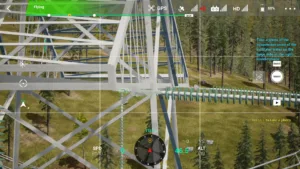 | |
| 49 | Right Middle Phase, Jumper String Cross-arm End Hanger | Photograph the connecting hardware at the lower end from a horizontal angle; take a top-down shot of bolts and pins above the hanger. Hardware should occupy at least 50% of the photo. |  | |
| 50 | Right Middle Phase, Jumper Insulator | Capture the full insulator; each shed must be clearly identifiable. | 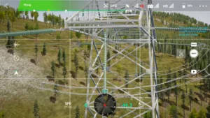 | |
| 51 | Right Middle Phase, Jumper String Conductor End Hanger | Take two photos from small-side and large-side conductor ends. Each photo must show the panorama from the insulator’s end cup to the damper, with hardware occupying at least 50% of the photo. | 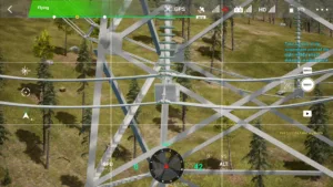 | |
| 52 | Right Middle Phase, Large-side Insulator Cross-arm End Hanger | Bolts, nuts, locking pins, and small hardware must be clearly visible. Use multiple angles if equipment overlaps. Each photo should include at least one insulator. | 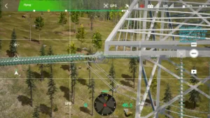 | |
| 53 | Right Middle Phase, Large-side Insulator | Cover the full insulator string; multiple photos may be taken to clearly show surface damage and connections of each insulator. |  | |
| 54 | Right Middle Phase, Large-side Insulator Conductor End Hanger | Bolts, nuts, locking pins, and vibration dampers must be clearly visible. Use multiple angles if equipment overlaps. Each photo should include at least one insulator. |  | |
| 55 | Right Lower Phase, Small-side Insulator Conductor End Hanger | Bolts, nuts, locking pins, and vibration dampers must be clearly visible. Use multiple angles if equipment overlaps. Each photo should include at least one insulator. |  | |
| 56 | Right Lower Phase, Small-side Insulator | Cover the full insulator string; multiple photos may be taken to clearly show surface damage and connections of each insulator. |  | |
| 57 | Right Lower Phase, Small-side Insulator Cross-arm End Hanger | Bolts, nuts, locking pins, and small hardware must be clearly visible. Use multiple angles if equipment overlaps. Each photo should include at least one insulator. |  | |
| 58 | Right Lower Phase, Jumper String Cross-arm End Hanger | Photograph the connecting hardware at the lower end from a horizontal angle; take a top-down shot of bolts and pins above the hanger. Hardware should occupy at least 50% of the photo. |  | |
| 59 | Right Lower Phase, Jumper Insulator | Capture the full insulator; each shed must be clearly identifiable. |  | |
| 60 | Right Lower Phase, Jumper String Conductor End Hanger | Take two photos from small-side and large-side conductor ends. Each photo must show the panorama from the insulator’s end cup to the damper, with hardware occupying at least 50% of the photo. | 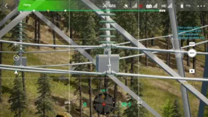 | |
| 61 | Right Lower Phase, Large-side Insulator Cross-arm End Hanger | Bolts, nuts, locking pins, and small hardware must be clearly visible. Use multiple angles if equipment overlaps. Each photo should include at least one insulator. |  | |
| 62 | Right Lower Phase, Large-side Insulator | Cover the full insulator string; multiple photos may be taken to clearly show surface damage and connections of each insulator. | 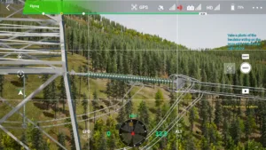 | |
| 63 | Right Lower Phase, Large-side Insulator Conductor End Hanger | Bolts, nuts, locking pins, and vibration dampers must be clearly visible. Use multiple angles if equipment overlaps. Each photo should include at least one insulator. |  | |
| 64 | Small-side Passage | The tower passage should be fully visible, including buildings, trees, crossing points, and lines being spanned. | 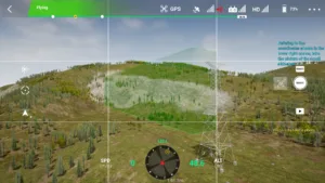 | |
| 65 | Large-side Passage | The tower passage should be fully visible, including buildings, trees, crossing points, and lines being spanned. |  |

0%
Loading ...