500 kV Pull Tower: Key Inspection Points and Standards
Simon.Srizfly
Table of Contents
The 500 kV pull tower is a critical component in high-voltage power transmission, ensuring the stability and safety of the entire line. Proper inspection of these towers is essential to identify potential structural issues, hardware wear, and conductor conditions before they lead to operational failures. This guide outlines the key inspection points and industry standards, providing a comprehensive reference for engineers and UAV inspection teams to maintain the reliability and efficiency of 500 kV transmission lines.
Serial Number
Inspection points
Shooting quality requirements
Software checkpoint screenshot
Real Inspection Point Images
1
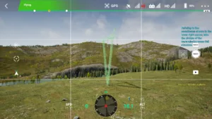
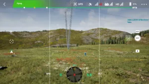
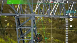
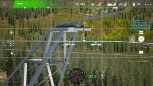
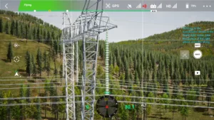
Full Tower View
The full tower view should be complete, clearly showing tower materials and angles, with the main subject occupying at least 80% of the vertical frame.
1 500kv pull tower full view drone inspection simulator
2
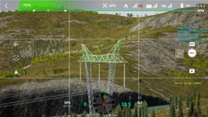
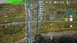
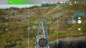
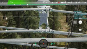
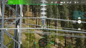
Tower Head
The tower head must be fully visible.
2 500kv pull tower top section drone inspection simulator
3
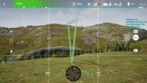
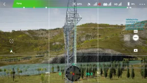
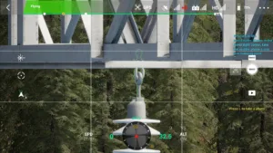
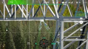
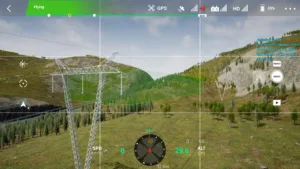
Tower Body
All structures except the tower head and tower base must be visible.
3 500kv pull tower body structure drone inspection simulator
4
Pole Number Plate
The dual-line names on the pole number plate must be clearly distinguishable.
4 500kv pull tower pole number plate drone inspection simulator
5
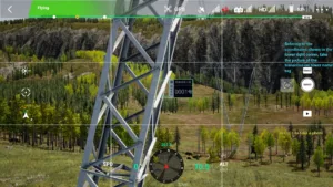
Tower Base and Ground Guy Wires
The ground condition near the tower base must be clear, and guy wires must be firmly connected.
5 500kv pull tower base and ground wire drone inspection simulator
6
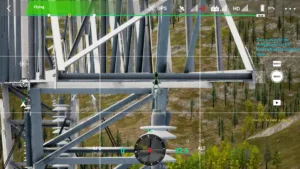
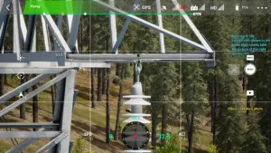
Left Phase Conductor End Hanger
Bolts, nuts, locking pins, and vibration dampers must be clearly visible. Use multiple angles if equipment overlaps. Each photo should include at least one insulator.
6 500kv pull tower left phase conductor end drone inspection simulator
7
Left Phase Insulator String
The full insulator string must be covered. Multiple photos may be taken to clearly show surface damage and connections of each insulator.
Bolts, nuts, locking pins, and small hardware must be clearly visible. Use multiple angles if equipment overlaps. Each photo should include at least one insulator.
8 500kv pull tower left phase cross arm point drone inspection simulator
9
Left-side Guy Wire Hanger
Bolts, nuts, locking pins, and small hardware must be clearly visible. Use multiple angles if equipment overlaps.
9 500kv pull tower left guy wire anchor drone inspection simulator
10
Left-side Ground Wire
The combination installation of all hardware must be identifiable, as well as the aluminum tape installation at contact points. Nuts and pins at locking positions must be clearly visible. Use multiple angles if equipment overlaps.
10 500kv pull tower left ground wire drone inspection simulator
11
Middle Phase Cross-arm Hanger
Bolts, nuts, locking pins, and small hardware must be clearly visible. Use multiple angles if equipment overlaps. Each photo should include at least one insulator.
11 500kv pull tower middle phase cross arm point drone inspection simulator
12
Middle Phase Insulator String
The full insulator string must be covered. Multiple photos may be taken to clearly show surface damage and connections of each insulator.
Bolts, nuts, locking pins, and vibration dampers must be clearly visible. Use multiple angles if equipment overlaps. Each photo should include at least one insulator.
The combination installation of all hardware must be identifiable, as well as the aluminum tape installation at contact points. Nuts and pins at locking positions must be clearly visible. Use multiple angles if equipment overlaps.
14 500kv pull tower right ground wire drone inspection simulator
15
Right Phase Cross-arm Hanger
Bolts, nuts, locking pins, and small hardware must be clearly visible. Use multiple angles if equipment overlaps. Each photo should include at least one insulator.
15 500kv pull tower right phase cross arm point drone inspection simulator
16
Right Phase Guy Wire Hanger
Bolts, nuts, locking pins, and small hardware must be clearly visible. Use multiple angles if equipment overlaps.
16 500kv pull tower right guy wire anchor drone inspection simulator
17
Right Phase Insulator String
The full insulator string must be covered. Multiple photos may be taken to clearly show surface damage and connections of each insulator.
Bolts, nuts, locking pins, and vibration dampers must be clearly visible. Use multiple angles if equipment overlaps. Each photo should include at least one insulator.
18 500kv pull tower right phase conductor end drone inspection simulator
19
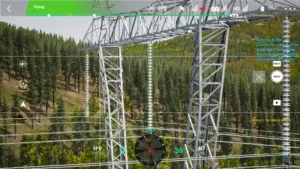
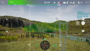
Small-side Passage
The tower passage should be fully visible, including buildings, trees, crossings, and lines being spanned.
19 500kv pull tower small side access path drone inspection simulator
20
Large-side Passage
The tower passage should be fully visible, including buildings, trees, crossings, and lines being spanned.
20 500kv pull tower large side access path drone inspection simulator